Introduction
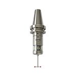
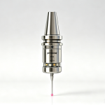
Radio Frequency (RF) machine tool probes have become indispensable in modern CNC machining environments. Unlike infrared (IR) probes, RF probes transmit measurement data via radio waves, eliminating the need for precise line-of-sight alignment between the probe and receiver. This makes them particularly well-suited for large-format machines, 5-axis machining centers, and gantry systems where physical obstructions and complex tool paths make IR alignment impractical. RF probes also support high-bandwidth scanning measurements, enabling real-time surface contouring and complex GD&T analysis directly on the machine tool.
However, like any precision measurement system, RF probes can encounter operational issues — from LED indicator anomalies and signal feedback errors to alarm codes that halt production. A thorough understanding of these common problems and their solutions can significantly reduce machine downtime and extend probe service life.
This guide covers the most frequently encountered RF probe application issues and provides step-by-step troubleshooting procedures to help CNC operators and maintenance technicians resolve them quickly and effectively.
1. Probe LED Flashing or Staying On
① Flashing 5 Consecutive Times
Indicates low battery. Replace the battery immediately.
② LED Stays Constantly On
If the LED remains on continuously and stays illuminated for approximately 30 seconds after the battery is removed, this indicates an internal hardware fault. Return the probe to the factory for repair.
2. Receiver Signal Feedback Stuck at “1” (Not Switching to “0”)
Cause: The red wire (24V) and the red-white wire (0V) are wired in reverse.
Solution: Reverse the wiring connections of the red wire and the red-white wire.
Caution: Do NOT connect both wires to the 24V terminal simultaneously — this will cause a short circuit in the receiver and may result in permanent damage.
3. Receiver Red LED Stays On
Follow these steps in order:
- Point the probe directly at the receiver and trigger it manually by touching the stylus.
- If there is no response, verify that the probe and receiver ID numbers match.
- Reduce the distance between the probe and the receiver.
4. Probe LED Lights Up for ~30 Seconds After a Single Touch, Then Turns Off
Possible Cause: The grease inside the probe mechanism has become too viscous, increasing mechanical resistance.
Solutions:
- Manually deflect the stylus through a large range of motion several times to redistribute the grease.
- If the issue persists, return the probe to the factory for maintenance.
5. Common Alarm Codes & Solutions
86 — PROBE OPEN
Possible Causes:
- The probe contacts an obstacle during a protected positioning move.
- Machine vibration during rapid traverse causes signal interference.
Solutions:
- Manually trigger the probe, or disable the probe command if applicable.
- Reset the program or restart the machine.
92 — PROBE OPEN
Possible Cause:
- During a double-trigger measurement, the probe fails to fully retract from the workpiece surface after the first measurement before the second measurement begins.
Solutions:
- Increase the retract distance parameter in the measurement program.
- On dual-channel machines, this may be a false alarm caused by signal detection overlap between channels. Use two separate measurement programs — one dedicated to each channel.
93 — PROBE FAIL
Possible Cause: Measurement signal not received by the receiver.
Solutions:
- Verify that the probe and receiver ID numbers match.
- If the probe is already in use, check whether the actual measurement points in the program are correct. Repeat the measurement — if alarm 93 persists, the issue is likely program-related.
- If neither of the above applies, suspect a hardware communication fault in the probe system.
Dual-Channel Machine Alarm: “Channel 1/2 — Probe Deflected, Cannot Send Pulse”
Solutions:
- Receiver installation:Ensure that each channel’s probe and receiver are mounted on the same side of the machine, and position the receivers inside the machine enclosure.
- Each channel must use its own dedicated measurement program — do not share a single measurement program between channels.
Pro Tips for RF Probe Reliability
- Battery management:Replace probe batteries on a regular schedule rather than waiting for a low-battery warning. A weak battery can cause intermittent signal loss.
- Signal path clearance:Although RF probes do not require line-of-sight alignment, large metal objects (such as fixture plates or workholding clamps) placed between the probe and receiver can still attenuate the signal. Maintain a clear RF path where possible.
- Regular calibration:Follow the manufacturer’s recommended calibration interval (typically every 6–12 months) and verify against a known standard such as a calibration artifact or master sphere.
- Connector inspection:Periodically inspect the probe-to-receiver electrical connectors for wear, contamination, or corrosion, and clean with appropriate contact cleaner if necessary.
Need further assistance? If the troubleshooting steps above do not resolve your issue, contact our technical support team with your probe model number and a description of the problem. Our engineers are available to provide remote diagnostics or arrange factory service.
You May Like
 What is a mill touch probe?
- What is a cnc tool setter and how does it work?
- What is broken tool detection and why it matters in modern cnc machining?
- IR Touch Probe (JPM50/JPM60)
- RF Touch Probe (JPM400/JPM46M)
- Infrared vs. Radio Frequency Machine Tool Probes: A Comprehensive Buyer’s Guide
- Stylus For Touch Probe