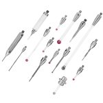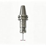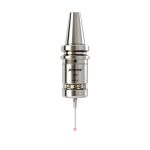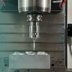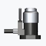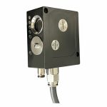
Selecting the right machine tool probe is one of the most impactful decisions for improving CNC machining accuracy, efficiency, and automation. The probe you choose directly affects setup time, part quality, machine utilization, and long-term maintenance costs.
For most buyers, the first major decision is straightforward: Infrared (IR) or Radio Frequency (RF)? This guide explains the practical differences between these two wireless transmission technologies, outlines critical technical specifications, and helps you determine which solution is the best fit for your specific manufacturing environment.
What Is a Machine Tool Probe?
A machine tool probe is a precision measuring device mounted inside the machine tool spindle or turret. It is primarily used to: - Set workpiece origins automatically - Measure tool length and diameter - Verify part dimensions during or after machining - Compensate for thermal drift and fixture variation - Enable in-process inspection
Probes eliminate manual setup errors, reduce scrap rates, and allow machines to run unattended for longer periods.
Touch-Trigger vs. Scanning: Choosing the Right Measurement Style
Before selecting a transmission technology, it is essential to distinguish between the two primary measurement styles:
- Touch-Trigger Probes:These operate by making physical contact with the workpiece to trigger a signal. They are highly robust, cost-effective, and ideal for standard workpiece setup, tool setting, and general in-process gauging. Both IR and RF technologies are widely available in touch-trigger formats.
- Scanning Probes:These continuously measure the surface contour by sweeping a stylus across the part. They provide significantly higher point density and are necessary for complex freeform surfaces, high-precision mold/die validation, and detailed geometric dimensioning and tolerancing (GD&T) analysis. Scanning probes typically rely on RF transmission due to the higher data bandwidth required.
Infrared vs. Radio Frequency: Technical Comparison
Modern touch-trigger and scanning probes communicate with the CNC control through one of two wireless methods. Understanding their technical distinctions is critical for reliable operation.
| Feature | Infrared (IR) Probe | Radio Frequency (RF) Probe |
| Signal Type | Infrared (IR) | Radio Frequency (RF) |
| Receiver Placement | Near the machine work area; line-of-sight required | Flexible; can be mounted away from the machine |
| Typical Range | 1–3 meters | Up to 15 meters |
| Best For | Small-to-medium VMCs/HMCs with clear optical paths | Large gantries, 5-axis machines, and obstructed environments |
| Obstruction Tolerance | Low; requires a clear optical path | High; penetrates fixtures, castings, and machine structures |
| Coolant/Chip Resistance | Optical windows require periodic cleaning | Unaffected by coolant, mist, or heavy chip generation |
| Typical Accuracy | ±1–2 μm (2σ) | ±2–3 μm (2σ) |
| IP Protection Rating | Typically IP67 or IP68 | Typically IP67 or IP68 |
| Relative Cost | Lower initial investment | Higher initial investment |
| Installation Complexity | Requires precise alignment between receiver and probe; fiber optic extension available to ease positioning | Pairing-based; highly flexible receiver placement |
How to Choose: A Practical Framework
1. Evaluate Machine Size and Geometry
- Choose an Infrared Probe when:You operate vertical or horizontal machining centers with moderate travels, and the receiver can be placed with a guaranteed clear line of sight to the probe.
- Choose an RF Probe when:You operate large gantry mills, boring mills, or 5-axis machines where machine structures, fixtures, or workpieces frequently block the signal path, or when the receiver must be mounted far from the cutting area.
2. Consider Your Working Environment
- Infrared Probes work best in:Clean or lightly contaminated environments, applications with minimal coolant mist and chip spray, and dry cutting operations.
- RF Probes are better suited for:Heavy cutting with high-pressure coolant, applications with heavy chip generation, and environments where optical windows would foul quickly.
3. Match the Probe to Your Measurement Tasks
| Application | Recommended Technology |
| Precision workpiece setup and tool setting on small-to-medium machines | Infrared |
| Large casting or weldment alignment | Radio Frequency |
| 5-axis machining with complex rotary axis movements | Radio Frequency |
| High-precision mold and die work in clean conditions | Infrared |
| Heavy-duty roughing and in-process verification | Radio Frequency |
4. Evaluate Total Cost of Ownership (TCO)
While infrared probes generally have a lower purchase price, RF probes may deliver lower long-term costs in harsh or complex environments due to reduced cleaning, maintenance, and downtime. Key cost factors to compare include: - Initial hardware cost - Receiver installation and alignment time - Battery replacement frequency and cost - Cleaning and preventive maintenance labor - Potential downtime from signal interruption
Key Specifications to Review Before Buying
Before finalizing your selection, confirm these critical parameters with your supplier:
- CNC Compatibility:Ensure both the receiver hardware and the probing software/syntax are supported. Verify compatibility with your specific CNC control (Fanuc, Siemens, Heidenhain, Mazak, etc.) as well as third-party measurement software platforms (e.g., Renishaw TP-Link, PC-DMIS, VERICUT).
- Repeatability:Look for real-world repeatability values under your expected cutting speeds and feed rates, not just ideal catalog specifications.
- Stylus Parameters:Evaluate the stylus radius, trigger force (lateral and axial), and overall system stiffness. These factors directly influence measurement uncertainty, especially when probing delicate features or using long stylus extensions.
- Calibration Standards and Traceability:Confirm that the probe system is calibrated to recognized international standards, such as ISO 10360 or VDI/VDE 2617. Ensure the supplier provides traceable calibration certificates.
- Battery Life:Consider whether the probe uses standard or proprietary batteries and assess the ease of replacement in a production environment.
- Service and Calibration:Probes are precision instruments. Check local service availability, repair turnaround times, and recommended calibration intervals.
- Data Connectivity:If you plan to integrate probing data into a smart manufacturing or Industry 4.0 system, verify available communication protocols and data export formats.
Real-World Application Example
Consider a mold and die manufacturer machining complex cavity geometries on a 3-axis machining center. By integrating an infrared touch-trigger probe, the shop achieved automated in-process verification of critical cavity dimensions between finishing passes. Because the shop maintained strict coolant filtration and chip management, the IR probe’s optical window remained clear, enabling reliable closed-loop compensation and reducing post-machining CMM inspection time by 40%. This demonstrates that when environmental conditions are controlled, IR probes deliver exceptional value in precision applications.
Maintenance Best Practices
To ensure long-term reliability, adhere to the following maintenance routines: - Infrared Probes: Regularly clean the optical transmitter and receiver windows using approved, lint-free wipes and recommended solvents. Inspect for scratches or pitting that could degrade signal integrity. - RF Probes: Periodically inspect the RF antenna and coaxial connections for physical damage, corrosion, or loose fittings. Ensure the antenna is not obstructed by metallic debris. - General: Monitor battery voltage regularly and replace batteries proactively to prevent mid-cycle signal loss. Follow the manufacturer’s recommended calibration schedule to maintain measurement traceability.
Safety Considerations
- Moving Parts:Never attempt to install, remove, or service a probe while the machine spindle is rotating or the axes are in motion. Always follow lockout/tagout procedures during receiver installation.
- Electrical Safety:Ensure all receiver and interface connections are properly grounded and shielded to prevent electrical interference with the CNC control.
- Collision Protection:Always use a stylus with an appropriate collision protection mechanism (e.g., kinematic mount or electronic overload protection) to prevent catastrophic damage to the probe or spindle in the event of an unexpected crash.
Limitations of Each Technology
No technology is universally superior. Buyers should acknowledge the inherent limitations of each: - Infrared Limitations: IR probes are strictly dependent on line-of-sight. Any obstruction—whether from a fixture, chip pile-up, or heavy coolant fog—will cause immediate signal loss. They are not suitable for applications where the probe must operate behind machine structures. - RF Limitations: RF probes have a higher initial cost and can be susceptible to electromagnetic interference (EMI) in shops with poorly shielded high-power equipment. Their longer range also means they can potentially receive stray signals from adjacent machines if not properly configured.
Quick Summary
Small machines, clean environments, and cost-sensitive applications tend to favor infrared machine tool probes. Large machines, complex geometries, heavy coolant, and harsh conditions tend to favor radio frequency (RF) machine tool probes. The best probe is the one that reliably transmits accurate data in your actual machining environment.
Need Help Choosing?
Every shop and every machine is different. If you would like a recommendation based on your specific machine model, workpiece types, and production goals, contact our technical team. We can help you select the right probe and verify full CNC compatibility before you order.
For more CNC measurement solutions and application guides, visit our website at cncjoyoshine.com or email us at jom.lin@joyoshine.com.
You May Like
 Stylus For Touch Probe
- Troubleshooting Guide for Radio Frequency (RF) Machine Tool Probes: Common Issues & Solutions
- IR Touch Probe (JPM50/JPM60)
- CNC technical support Serbia, Minth Group CNC service, dual-channel CNC, on-machine probing, NEV manufacturing, Joyoshine global service
- What is a mill touch probe?
- What is a cnc tool setter and how does it work?
- What is broken tool detection and why it matters in modern cnc machining?